Installation and wiring
Practical installation rules for Edge charge controllers and site controllers. Bus cable, addresses, jumpers, DC leakage wiring, CT clamps, P1 connection, and the checks after power-up.
View as MarkdownUpdated 2026-10-26
The step-by-step guides with figures are the installation manuals, one per site controller: with CT clamps (EVSE-SC-01) and on the smart meter (EVSE-SC-02). This page lists the rules in short.
Work in the distribution board and new circuits for charge points must be done by or under a qualified electrician under NEN 1010 (IEC 60364-7-722).
RS485 bus
| Rule | Why |
|---|---|
| Cable: 3 × 0.75 mm², multi-core (stranded), for GND, A+ and B− | Stranded cores survive bending and movement at the terminals |
| No solid-core cable | Solid cores break at the terminal when the cable is bent or moved |
| No raw Ethernet cable (Cat5/6, UTP) in screw or push-in terminals | Thin solid cores, clamped without strain relief and bent tightly, break sooner or later |
| Ethernet cable only with connectors fitted | Use a patch cable with RJ45 plugs at both ends; we supply a small adapter board with an RJ45 socket that the bus wires are soldered to, on request |
| Bus topology, one cable passing every device | Stubs cause reflections |
| No Modbus over Ethernet or wireless Modbus with a site controller | The board expects an answer within 40 ms; a TCP gateway works in principle but answers too slowly for EdgeTech site controllers |
Charge controller
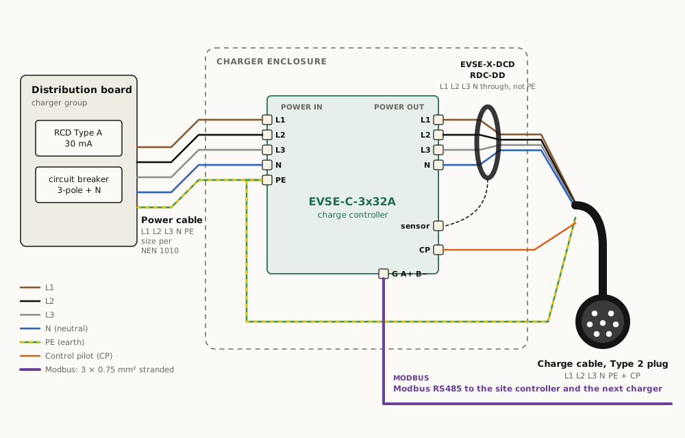
- Jumper top right: open = 16 A maximum, shorted = 32 A maximum.
- Modbus address is 1 as shipped. Address 1 is special: after boot the board only answers after a state change (the button, or plugging in a car). A site controller moves each new board to its own address; with your own controller, write 2, 3, 4… to register 0x0200.
- 1-phase installation: PE, N and L1 only; set PHASES bit 0 in the Settings register (or
settings@<socket>= 0 from the platform). - Route N and the connected phases through the EVSE-X-DCD toroid. Not PE.
- Mount so the board temperature stays below 62 °C in summer. Above that it limits to 10 A.
- First power-up: the board self-tests earth, neutral and L1. A green blink about every 3 s means healthy.
Site controller SC-01 (clamps)
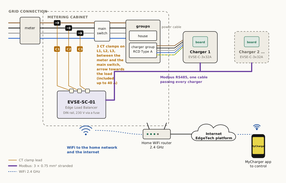
- In the distribution board, behind a fuse, on 230 V.
- Clamps C1, C2, C3 on L1, L2, L3 of the main connection, between the meter and the main switch, arrow towards the load. The 3 included clamps measure up to 40 A; CTs for higher currents (on request) have a different ratio and must be selected in the app.
- 1-phase site: one clamp on L1, on the same phase as the charge point.
Site controller SC-02 (P1)
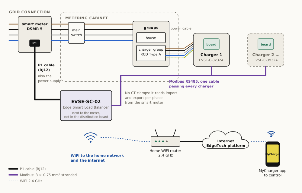
- Next to the meter, not in the distribution board. RJ12 into the P1 port.
- If the P1 port is already in use: powered splitter. If the meter delivers less than 250 mA: micro-USB supply.
- WiFi 2.4 GHz. Hold the Mode pinhole 3 s to start setup, then pair in MyCharger.
- Restart: pull the RJ12 for 3 s.
GridShield
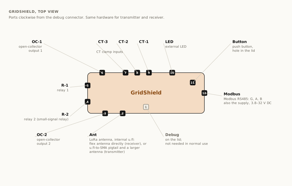
The same box works as a transmitter or a receiver. Ports, clockwise from the debug connector on the lid:
| Port | Use |
|---|---|
| Debug | Not needed in normal use |
| Ant | LoRa antenna on an internal u.fl connector, through a hole in the casing: a flex antenna directly (receiver), or a u.fl-to-SMA pigtail and a larger antenna (transmitter) |
| OC-2, OC-1 | Open-collector outputs 2 and 1 |
| R-2, R-1 | Relays 2 and 1 (internal small-signal relays) |
| CT-3, CT-2, CT-1 | CT clamp inputs |
| LED | External LED |
| Button | Push button, through a hole in the lid |
| Modbus | Modbus RS485 |
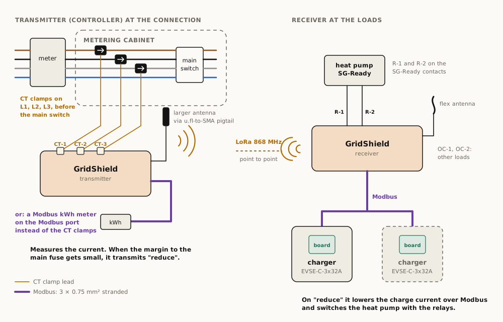
Transmitter (controller), at the grid connection
- Measure the current: a Modbus kWh meter on Modbus, or CT clamps on CT-1 to CT-3.
- Fit the antenna that suits the distance to the receivers.
- It monitors the current and starts transmitting “reduce” when the margin gets small.
Receiver, at the loads
- Fit the antenna that suits the distance to the transmitter.
- Connect what has to reduce its energy use: chargers over Modbus, an SG-Ready heat pump on the relays.
Matter over Thread
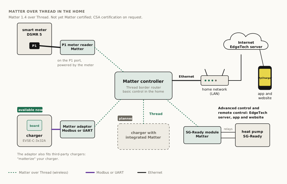
- P1 meter reader: on the P1 port of the DSMR 5 smart meter, which also powers it.
- Charger: a Matter adaptor on the charger over Modbus or UART (available now; also fits third-party chargers). A charger with integrated Matter is planned.
- Heat pump: the SG-Ready module’s relays on the heat pump’s SG-Ready contacts.
- Matter controller: Ethernet to the home network and the internet. Basic control runs on the controller; advanced control and remote control on the EdgeTech server, app and website.
- Certification: Matter 1.4 over Thread, not yet Matter certified; CSA certification on request.
After power-up
| Check | Expected |
|---|---|
| Charge controller LED | Green blink every ~3 s |
| Site controller in the app | Online, firmware version shown |
mb_quality in site status |
> 95 % |
| Plug in a car | State B, then C when a session starts; current per phase visible |
| DC leakage test button (if fitted) | Charging relays open within 300 ms, error bit 5 (value 32) |